
Many years ago, while in college, I purchased a stereo system for my dorm room. I updated and added to it slightly after graduation, but mostly, these are the pieces that I bought while I was an undergrad.
Recently. I burned out my speakers, which started an entire process of repairs and updates. Here are a few of the repairs.
The first problem to resolve was the burned out speakers. Checking, the amplifier's speaker outputs, the left channel showed a significant DC voltage present that floated around 30VDC. There never should be DC voltage present on the speaker outputs. Checking the preamp's output, there was no DC voltage present; therefore, the problem was in the power amp. Making it necessary to open the amp and backtrack the source of the voltage. I was figuring a bad transistor or a bad resistor throwing off a bias voltage.
The amp is modular. There are two identical board sets for the left and right channels. The easiest thing was to measure the signal going into and coming out of each module. There was DC voltage going into the left channel amp module, which isolated the problem to the input board.
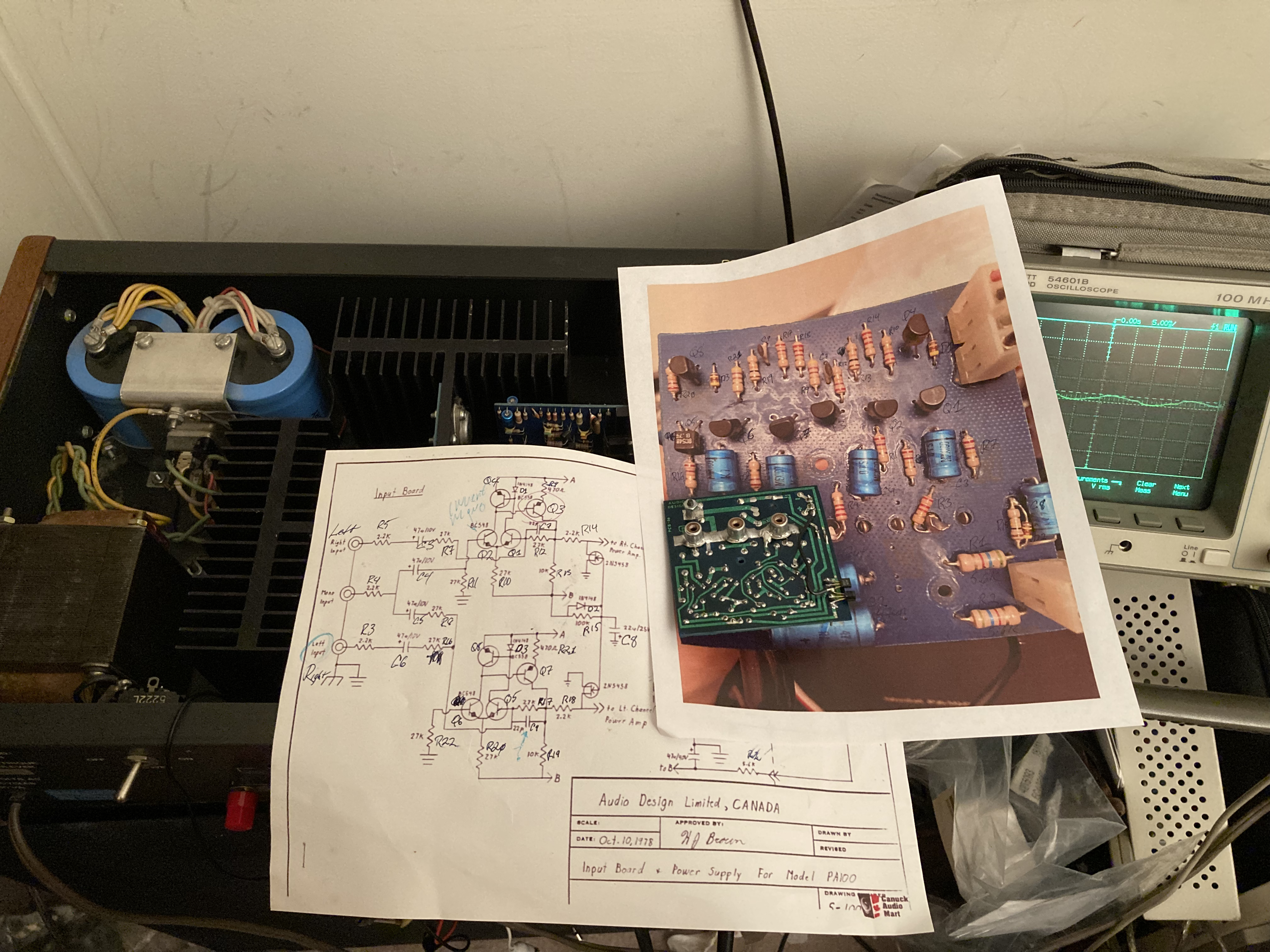
Others posted the schematic for the Audio Design PA100 on-line. Unfortunately, it's a bare schematic without voltages or a board layout. Thus the first task was to create a parts layout diagram. I photographed the input board top and bottom and printed a copy of the schematic. Each component on the schematic was uniquely numbered and the part in the photo of the input board was hand traced and marked. After much time, I marked nearly the entire schematic and most of the parts of the input board.
Working backwards from the output terminal of the input board, I checked for DC voltage on the emitter and base of each transistor in the signal path to find the problem's origin. Surprisingly there was DC voltage at every transistor on the input board for the left channel.
There was DC voltage on the base of the transistor I marked as Q2. Checking R11, it was fine, but not grounded. Examining the board more closely, I saw that R11 is grounded to the trio of RCA connectors that connects the amp to the preamp. When they manufactured the input board, they did not bend the tabs for the RCA connectors which put all of the strain of plugging and unplugging the cables on the solder connection. I suppose it flexed one time too many, which broke the connection. Bending the tabs to anchor the terminals more solidly and re-soldering the ground connections solved the problem.
To ensure that the problem was fixed before risking another set of speakers, I connected 8Ω 20W resistors to the output terminals and played the amp for a few hours while monitoring the output with a voltmeter and oscilloscope. I didn't turn the volume up too high. the PA100 can dump 100W with as much as 20 amps of current into the output terminals. I didn't want to overheat the test resistors. No DC voltage was present whether the amp was run gently or hard.
Problem solved!
- Log in to post comments