
1983 Imperial EFI control pump
Reassembling the EFI system on Isabella, my 1983 Imperial, I noted that the EFI system's control pump was not working, which meant that disassembling and cleaning would be necessary. Since the pump wasn't working, and the car wouldn't work without it, I plunged ahead with trepidation, because this procedure is undocumented. Chrysler intended that dealers and repair facilities would simply swap the entire Hydraulic Support Plate for a new or rebuilt one and a rebuilder would perform these repairs. Without there being any rebuilders 34 years later, that task fell to me.
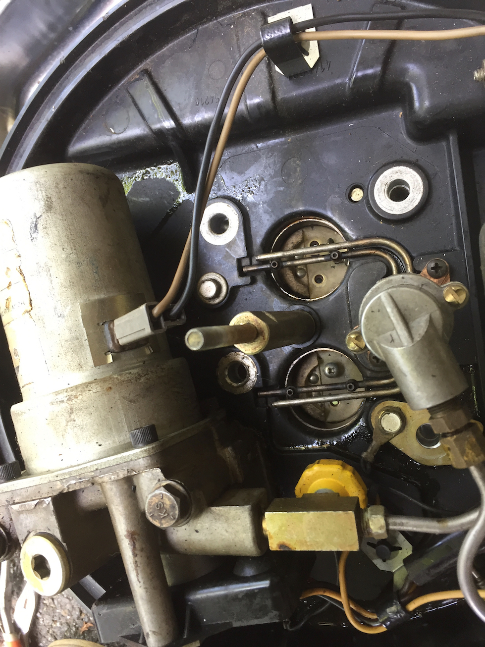
Once removing the pump from the Hydraulic Support Plate, I removed the fuel flowmeter and fuel temperature sensor module. The Control Pump dominates the picture below that shows about half of the Hydraulic Support Plate. The sensor module is the black part at the bottom of the following photo. Once that's removed, the pump head is removed from the body. The head contains check valves as well as the connection for the fuel line from the in-tank electric fuel pump, a connection for the return line, and the feed to the injection spray bars. The fuel supply and return connections are below, beneath the Hydraulic Support plate. The line to the injectors is to the right. Mounted on the underside of the connector, is a pressure sensor, which is painted yellow. The pressure sensor runs the control pump at full speed to purge fuel vapor from the system before starting. The pressure sensor shuts down once pressure starts to accumulate.
Without the head, the vanes and rotor of the pump are visible. I had to remove this as well to properly clean and free the pump's motor. Cleaning was straightforward. But reassembling vane pumps is a task that tries one's patience!
Here are the parts of the vane pump.
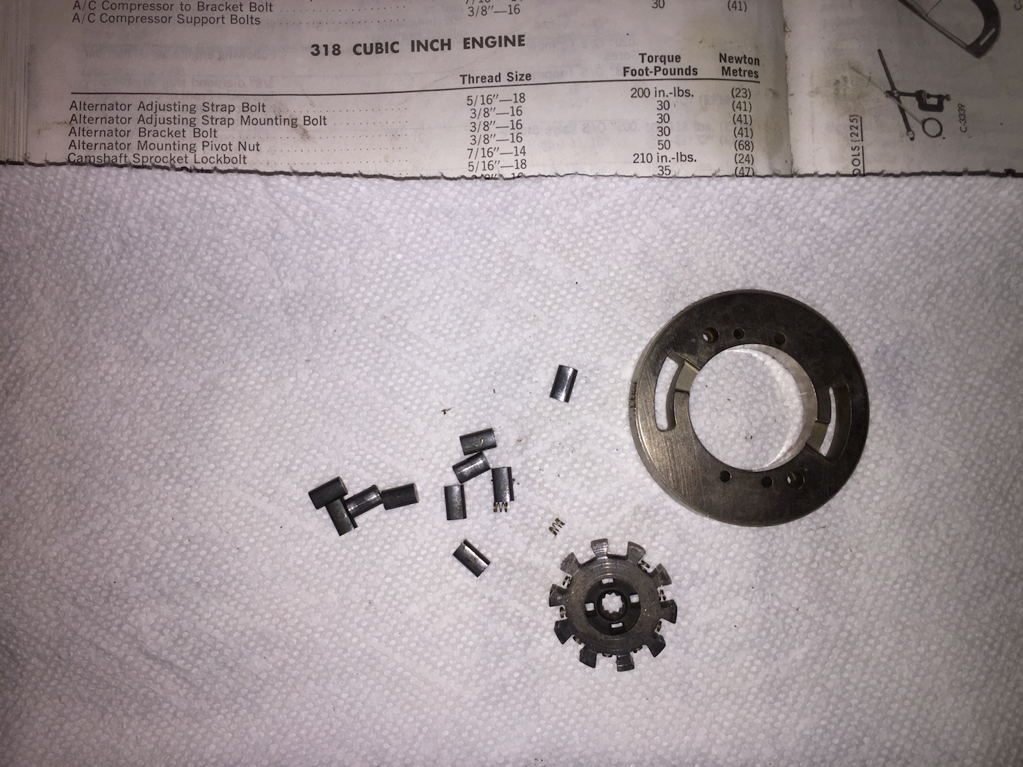
Here are the working parts of the control pump. The motor shaft has a spline that engages the splined rotor and spins it. The vanes contact the ring and, since the rotor is mounted eccentrically, the space between the rotor and ring changes. With the vanes forming a spaces that is increased and reduced, it pumps fuel from where the space is large to where the space is small.
The trick here is to put all of the springs in place, then the vanes against the springs and finally to slip that into the center of the steel ring, which is shown on the right side of the image. This, as you might guess, is a non-trivial operation unless one has a good technique. My solution to the problem follows.
I bent a small piece of steel wire into an L shape with the bottom of the L being only about the length of the springs. Using the wire, a small amount of grease is placed into each hole in the rotor to retain the springs. I used a grease without a lot of solids that would be soluble in gasoline and would therefore wash out without leaving a mess. The grease is important as it acts as a weak glue to hold the spring in place while doing the next step. Once all ten holes have a small amount of grease, I cleaned the wire that I used to place the grease into the holes because I did not want to springs to stick to the wire. Placing a spring onto the small end of the L shaped wire, I then placed a spring into a hole, which the grease retained. Here you see 8 of the springs in position on the rotor with 2 still remaining to be inserted. Note the small size compared to the print in the Factory Service Manual!
This is the tricky part. Hold the rotor about halfway into the steel ring. While holding the rotor in that position, I inserted a vane in each space between the spring and the ring. To make that a little easier, I tilted the rotor slightly so that the rotor was a little more shallowly inserted into the pump ring while inserting the vane.
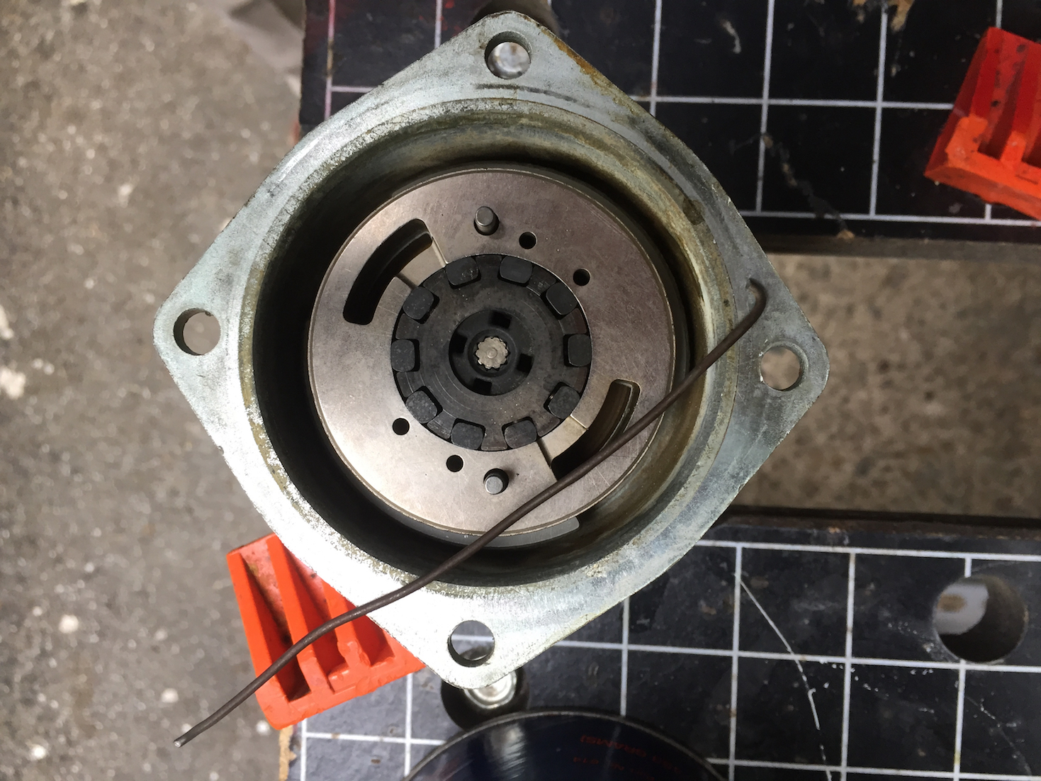
Once all the vanes are installed, the rest is easy. Turn the motor housing so that the armature is horizontal, then slip the rotor, vanes, and ring into place. The motor must be horizontal to keep the vanes and rotor from falling out. The Control Pump with the rotor assembly installed looks like this. The wire that I used to help assemble the pump is shown lying across the top of the pump.
Reassembling the rest was simple. The components are sealed with O rings, which are easily obtained. I used the same grease as before to retain the O ring in it's groove while assembling the pump head to the body. Grease is necessary because you do not want to invert the pump motor as the vanes and rotor will drop out. Using a little grease to hold the O ring, the pump head can be inverted and installed to the body.
So far, the pump seems to function well. Considering that these are made of unobtainium, it's important to know how to repair them.